Configuration and Engineering

ALOHA Cabled Observatory Installation
In this paper we provide an overview of the ACO system and instrumentation, the
installation operation, and a sample of initial data. Sensors now
connected to the ACO provide sound from local and distant sources and
measure currents, pressure, temperature and salinity.
The Communications protocol used in ACO is described in this paper.
The power system is described in this paper.
Additional technical description of the system is given in Praxis.
The detailed Schematics of the ACO are provided here.
Operational Status:
Two video cameras and three lights are working. The original pressure sensor in the Hydrophone Experiment Module is drifting dramatically. The new Basic Sensor Package was installed with a CTD, and ADCP, a fluorometer, a pressure sensor, and an acoustic modem. The fluorometer failed due to a ground fault. The pressure sensor is not communicating with the logger; a cable is suspected. The CTD with an oxygen optode is working, as is the ADCP and the modem.
Observatory Configuration
The ALOHA Cabled Observatory (ACO) is one of but a handful of seafloor
observatories worldwide connecting deep-sea science directly to the
researchers who are working to understand the complex processes that
occur there. This is a graphic description of the different modules that
are part of the ACO.
For photos and descriptions of each module, click here.
This paper describes the communications protocol used in ACO.
Instrumentation
The ACO is a prototypical example of a deep ocean observatory system that uses a retired cable.
The ACO architecture uses highly reliable existing transoceanic cable systems to provide power
and communications bandwidth.
The ACO consists of various modules as shown in Figures 1 and
2
. A "junction box" (JBOX) is
connected to the telecom cable termination. The JBOX converts the telecom communications protocols to
standard 100 Mb/s Ethernet, and has as well a hydrophone experiment module (HEM) with two
hydrophones and a pressure sensor. Then the "observatory" (OBS) is connected to the JBOX.
The OBS converts the dc current on the cable to 48 V and 400 V, and distributes this, the
Ethernet, and timing signals to eight user ports. On the observatory are two acoustic Doppler
profilers (ADPs), a temperature/conductivity instrument (MicroCat), and a light.
Two additional modules are connected to the Observatory. The AMM (ALOHA-MARS Module) seafloor
secondary node
and the camera. The AMM provides four additional user ports and has two CTDO2s and a
fluorometer/turbidimeter (FLNTU). The camera
with two lights and a hydrophone is connected to the AMM node.
In addition, a 200 m tall
thermistor array/acoustic modem (TAAM) mooring system is installed. This
mooring system has 10 thermistors spaced vertically; these are
battery operated and recording data internally. This system is not connected to the Observatory.


Figure 1, Left. Diagram showing the layout of the ACO modules on the seafloor.
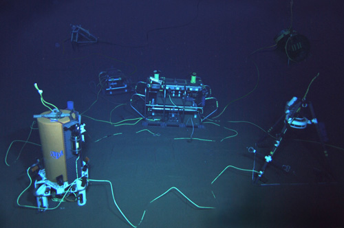
Figure 2, Right. Picture of the ACO (Observatory, JBOX, Camera and AMM) as deployed on the seafloor, taken by the Jason ROV.
(click on thumbnail to enlarge the image)

Top view of the ACO modules on the ocean floor. A mosaic of pictures taken by the Jason ROV during deployment.
(click on thumbnail to enlarge the image)

JBOX: The Junction Box (JBOX) converts the telecom communications protocols to standard 100 Mb/s Ethernet, and has as well a hydrophone experiment module (HEM) with one OAS (E-2PD) hydrophone, one "high frequency" home-made hydrophone and a Paroscientific, Inc (410K-101) pressure sensor.
(click on thumbnail to enlarge the image)

Observatory: The Observatory (OBS) is connected to the JBOX. On the observatory are two 250 kHz SonTek acoustic Doppler profilers (ADP1 and ADP2), a temperature/conductivity Sea-Bird SBE-37 MicroCat (CTD3), and a light. Note the port connectors (some covered by protective "enviromental covers" with orange paddles/handles).
(click on thumbnail to enlarge the image)

AMM: The ALOHA-MARS Module (AMM) seafloor secondary node has two Sea-Bird pumped MicroCats (SBE-52MP) measuring Temperature, Conductivity, Pressure and Dissolved Oxygen (CTD1 and CTD2); and a WETLabs Fluorometer/Turbidimeter ECO-FLNTURTD-2027 (FLNTU). This module also provides four additional user ports: 1 passing 400 V through, and 3 providing 48 V, along with 100 Mb/s Ethernet and a pulse-per-second signal
(click on thumbnail to enlarge the image)

Camera: An AXIS Communications 214 PTZ video camera (CAM) with two lights and a hydrophone mounted on a tripod are connected to the AMM.
(click on thumbnail to enlarge the image)

TAAM: The Thermistor Array/Acoustic Modem (TAAM) Mooring is 200 m tall and has 10 Sea-Bird SBE-39 thermistors spaced vertically recording data internally using batteries a WetLabs FLNTU fluorometer. It also has a WHOI acoustic-micromodem. The TAAM was deployed in June 2011 and recovered December 2012. Cable problems prevented connection to the ACO.
(click on thumbnail to enlarge the image)